"If all you have is a hammer, everything looks like a nail."
A familiar proverb that, as noted by Chris Hecker in his GDC talk, has an unappreciated cousin:
"If everything looks like a nail, all you need is a hammer."
Chris Hecker's message was that numerical optimization can solve a bunch of problems in the same way, as long as you set them up appropriately, making it a sort of hammer in your maths toolbox.
With increasing computer speed and a desire for rapid iteration, having a hammer readily available can be of great value, even if it doesn't solve the problem as cleanly or as run-time-efficiently as a purpose-designed solution, because it can save you a lot of programmer time. And, you can always move to a better solution after verifying it's a problem you want to solve.
One such problem, in computer vision, is figuring out how stuff is rotated and translated.
If you want to make a quadcopter land on a robot vacuum cleaner using a camera, part of the problem is calculating where you are relative to the robot, or where the robot is relative to you, so you know where you need to go.
If you want reconstruct a 3D model of a scene from photographs, part of the problem is calculating how the camera was rotated and translated between each photo. Using that you can triangulate the 3D coordinate of corresponding pixels by casting rays in the direction they came from and computing where the rays intersect.
Either way, calculating how your vacuum cleaner robot is positioned relative to your quadcopter, or how a camera moves through a scene as it takes photos of it, can both be turned into a type of optimization problem, a nail for our hammer.
However, it'll involve 3D rotations, which can be strange and annoying to deal with. This article tries to demystify literature on this topic.
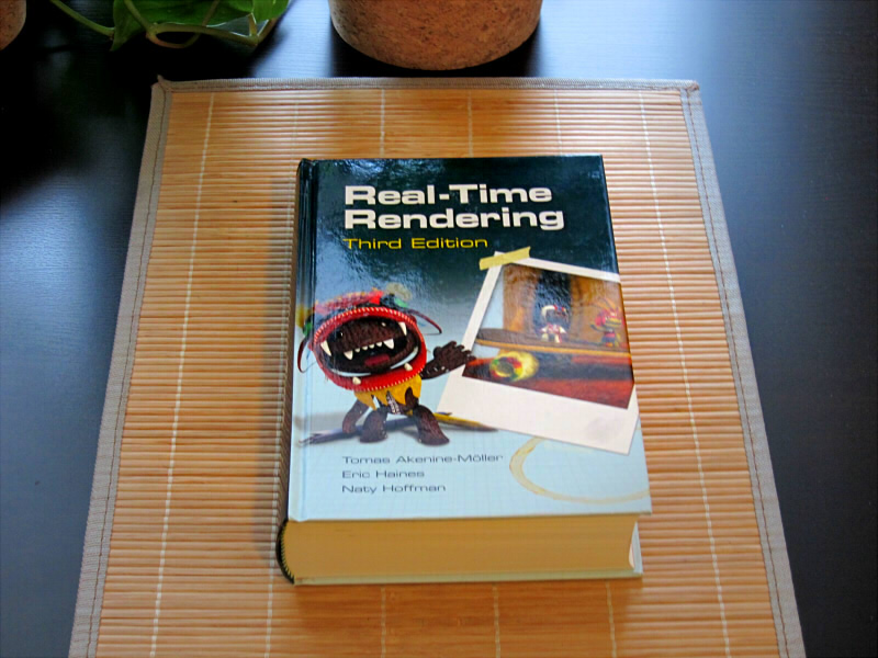
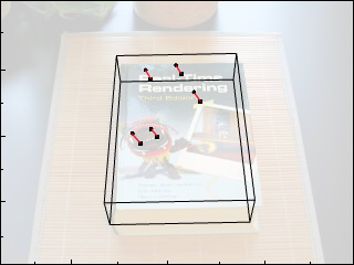
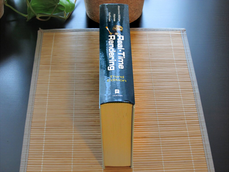
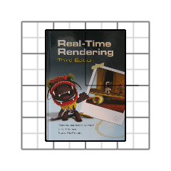
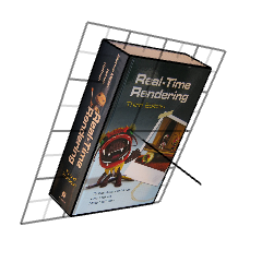
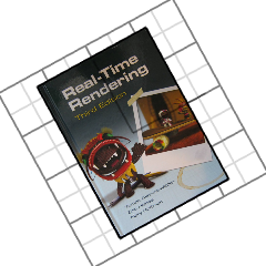
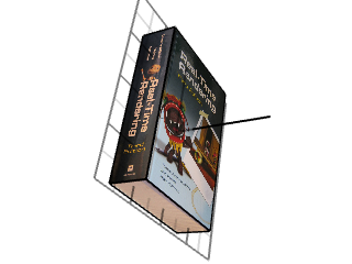
Books and CD covers are often used in impressive youtube videos of object tracking algorithms because they have unique textures that are easy to detect. Here's a book I picked from my shelf.
It's a pretty good book. One way to figure out how it is positioned relative to the camera (or vice versa) starts by finding matching patches of pixels between the photo and a 3D model.
At this point, your computer vision textbook will start to tell you about the Perspective-N-Point problem and show you how easily you can recover the rotation and translation matrices using linear algebra and Singular Value Decomposition...
...but that's an elegant solution.
We don't have time to learn about PnP, but we do know how to use a hammer and we don't care about efficiency right now, so let's turn this problem into a nail.
A nail version of this problem is similar to most nail versions of problems, and consists of
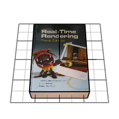
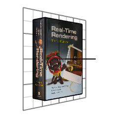
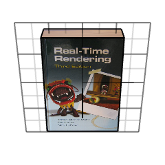
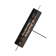
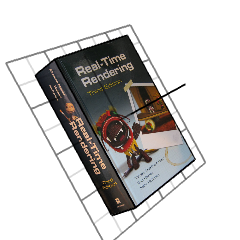
In our case, it means we guess the pose of the book to be some rotation and translation. To measure how bad our guess was, we can render the book as seen by my camera (a Canon S90 with heavy lens distortion).
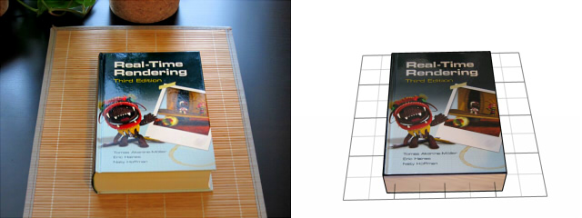
We can look at this as a person and say that looks pretty close, or not, but it's too slow to ask a person after each guess. If we want to automate this with a computer we need to be quantitative.
There are lots of ways to measure the quantitative quality of our guess, here's one that's pretty popular...
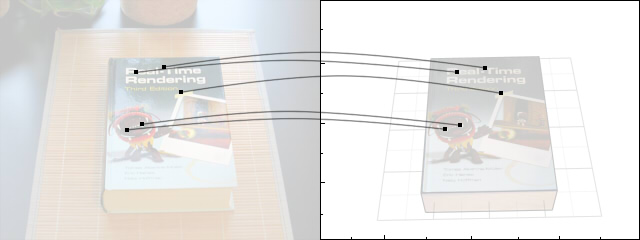
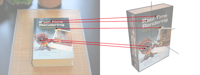
When we found pixel patches in the photograph and searched for matching patches in our 3D book, we got a bunch of 2D-3D correspondences: for each 2D patch coordinate in the photo, we have one 3D coordinate on the 3D box.
One measure of the quality of our guess is the average squared distance between those 3D coordinates (projected into the image) and their matching 2D coordinates.
In pseudo-code we could write this as
measure_quality(matrix3x3 R, vector3 T):
    e = 0
    for u,v,p in patches
        u_est,v_est = camera_projection(R*p + T)
        du = u_est-u
        dv = v_est-v
        e += du*du + dv*dv
    return e / num_patches
u,v is the 2D coordinate for each patch in the photo and p is the corresponding 3D coordinate. The 3D vector p is first rotated and translated from box coordinates into camera coordinates, and then transformed to a 2D vector by perspective projection.
Our quality measure is a function of the rotation and translation. Plug in R and T, get a value. The value is zero when the predicted 2D coordinates match the observed ones, and positive otherwise (in that sense we should call it a measure of error rather than quality). So if we want to find the true pose of the book, we just need to find values for R and T that make the error as small as possible.
How? Well with our hammer, of course!
There are many hammers to choose from, but gradient descent is simple to explain, and I mainly just want to make a point about rotations, not the hammers themselves. So bear with me for now.
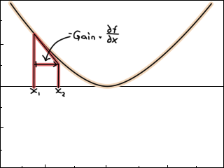
We want to adjust R and T to make the error smaller. One way to do so is to look at how the error changes for a change in R and T. For example, if we had the function f(x) = x^2, the derivative with respect to x (the gradient) says how the value of f changes for an increase in x. In this case, the derivative is dfdx(x) = 2x, so f will decrease as x goes from negative infinity to zero, and increase as x goes from zero to positive infinity..
The gradient is an indication of the direction we can adjust our parameters: If the gradient is positive, it means f increases for an increase of x (so we should decrease x); if the gradient is negative, f will decrease for an increase of x (so we should increase x).
One way to adjust x, starting from an initial guess, could therefore be x += -gain*dfdx(x).
This will make f(x) smaller and smaller until it stops, hopefully at zero. With some luck, the value of x at that point is even what you wanted. (Also likely is that it blows up to infinity, if you're not careful, but decent software packages do additional checks and number-massaging to prevent that)
The derivative of x^2 is simple, but it might take you longer than you'd like to differentiate more complex expressions, maybe involving matrices and stuff. Luckily we have some neat tools to do that for us, like automatic differentiation, symbolic processors (like MATLAB or Octave) or online matrix calculus tools.
But for now the simplest solution is to botch it with finite differences:
dfdx = (f(x+dx) - f(x-dx)) / 2dx
carefully selecting dx to be small enough, but not so small as to cause a floating point catastrophy. If you have a function with multiple arguments, like our error function, you take the derivative of each one:
dfdx = (f(x+dx, y, z) - f(x-dx, y, z)) / 2dx
dfdy = (f(x, y+dy, z) - f(x, y-dy, z)) / 2dy
dfdz = (f(x, y, z+dz) - f(x, y, z-dz)) / 2dz
This works for any ugly function you can reasonably code up. In fact, our error function is pretty ugly: it has matrix multiplications and a weird 3D-2D projection with lens distortion. It would surely be more efficient (runtime-wise) to derive an analytic expression, but the generality of finite differences makes it nice when you're pressed on time.
... but wait ...
How do we take the derivative with respect to a rotation matrix?
Ordinarily, a function of a matrix is not harder to differentiate than a function of a vector: it's just a bunch of numbers, and we can take the derivative with respect to each one. But a rotation matrix is not a bunch of numbers we can choose freely because not all 3x3 matrices are valid rotation matrices; there are constraints between the elements. i.e. the columns (or axes) of the matrix are perpendicular to each other and unit length.
What people usually do at this point is to parametrize the rotation matrix in terms of some other numbers that can be chosen freely, like Euler angles.
Euler angles are three numbers that represent three sequential rotations about three axes: x (1 0 0), y (0 1 0) and z (0 0 1). One possible such sequence is:
R = Rz(rz)*Ry(ry)*Rx(rx)
Euler angles is a so-called minimal parametrization, in that it uses the minimal amount of numbers (three) to define a rotation. By virtue of being minimal, those numbers can each be chosen freely, without concern of being constrained by the others.
That sounds like what we want, so let's add a function that takes three angles and returns a rotation matrix using some Euler angle sequence. In total we then have three variables for rotation (rx,ry,rz) and three variables for translation (tx,ty,tz). Because these six variables are all independent, we can update them with gradient descent, like so:
I abbreviated the quality measure function to E, for easier reading.
update_parameters(rx,ry,rz, tx,ty,tz):
    dedrx = (E(euler(rx+drx, ry, rz), [tx, ty, tz]) -
             E(euler(rx-drx, ry, rz), [tx, ty, tz])) / 2drx
         ...
    dedtz = (E(euler(rx, ry, rz), [tx, ty, tz+dtz]) -
             E(euler(rx, ry, rz), [tx, ty, tz-dtz])) / 2dtz

    rx -= gain*dedrx
    ry -= gain*dedry
    rz -= gain*dedrz
    tx -= gain*dedtx
    ty -= gain*dedty
    tz -= gain*dedtz
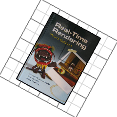
If you run this, it even looks like it's working:
It's a bit slow and unstable, but there are standard ways to speed things up and prevent taking too large steps (and you'll find these implemented in real optimization libraries). But aside from that, there is another problem here that is not obvious at first glance.
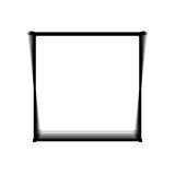
Consider a plate that you rotate around the x-, y- and z-axis in sequence (i.e. R = RzRyRx). Adjusting the angles in isolation produces these three motions (x on the left, z on the right):
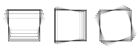
They all look clearly different, but a funny thing happens as the angle about the y-axis approaches 90 degrees. Here's an illustration: the left plate is rotating about x, the right plate about z, while you can control the rotation about y for both.
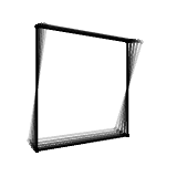
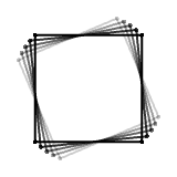
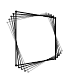
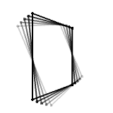
The two plates start out rotating about different axes, as you'd expect, but along the way, the right one mysteriously starts looking more and more like the left one, until they finally look identical (although in opposite directions).
What does this mean? Well here's a puzzle for you: try to rotate the book to match the photo.


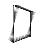
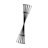
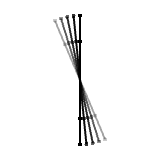
Although you start out able to produce three distinctly different motions, you can only produce two around that magical 90 degree sideways angle, and you are unable to get that backward pitch you are after. This drop in degrees of freedom from three to two is called gimbal lock and happens for any Euler angle sequence.
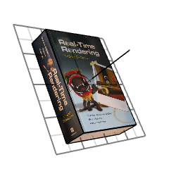
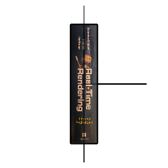
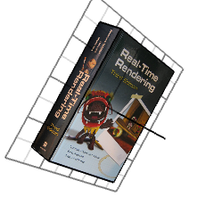
It's not as if we can't find three Euler angles to match the photo; I was just artifically limiting your input range. For example, (-90 45 -90) looks like this:
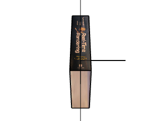
While we can always find a set of angles that exactly reproduce the photo (as there is no rotation Euler angles cannot describe), the problem, in the context of gradient descent, is that those angles can be unintuitively far away from our current guess. For example, if your current guess is (0 90 0)—head-on sideways
but the true rotation is at (-90 45 -90)—sideways and tilted slightly backward
then gradient descent will have trouble getting there, because neither of the motions you can produce with small changes of your parameters will tilt it backward; gradient descent only looks at how small adjustments increase or decrease the error in the small vicinity of our current estimate.
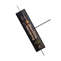
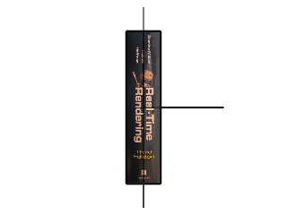
If those motions both increase the error, it means the optimization gets stuck, unable to progress. In fact, unless you can jump directly to the solution, getting there might involve things getting worse before getting better: an intermediate rotation, say at (-45 45 -45), will look like this
which is worse than the initial guess, so gradient descent will prefer to stay put. Alternatively, it'll start adjusting the wrong parameters, say, the translation, because they are the only ones that decrease the error.
![]()
For example, maybe there were relatively fewer point correspondences on the blank underside of the book than on the side, so that, in terms of the error, it is more beneficial to move the book up and back so as to align the ones on the side with each other.
In part two we'll actually get to the point and look at ways to solve the problem.
Improving gradient descent
When I made the gif of the book getting aligned with the photo, it did blow up on the first try. Popular optimization libraries employ an array of tricks and number massaging to prevent these sort of disasters, but it's still on you to parametrize your problem.
The lowest hanging fruit to improve gradient descent is to add a line search: instead of choosing an arbitrary step size (gain), you check the error at several points along the (negative) gradient direction and go to the point that had the lowest error. You still have to choose a min and max, but atleast the step size is not fixed arbitrarily.
Another low hanging fruit is to normalize your numbers. For example, the error function above expressed pixels in image coordinates (i.e. large numbers between 0 and 1280). When these are squared, you get really big floating point numbers which are then used to calculate the rotation and translation step (by multiplying by a very small number).
Finally, you might want to graduate from gradient descent and use something like Gauss-Newton or Levenberg-Marquardt.
How gimbal lock affects other optimization methods
I used gradient descent for this article because I didn't want too much mathematical baggage to get in the way, but I can't think of any paper that uses it on these types of problems (those involving pose estimation). More often I see people prefer Gauss-Newton or Levenberg-Marquardt.
Like gradient descent, these also calculate the gradient of the error, but the way they use it to step toward the solution is more involved, and assumes that the error function is a sum of squared errors (the type we looked at). Because of this they typically converge in fewer steps, although each step now requires more computation.
These methods are also affected by the gimbal lock problem, but the way it manifests itself is actually more evident than in gradient descent; in fact, the math tells you very clearly when it happens:
Skipping some details—because either you already know about these methods and you'll find it boring, or you don't know and a paragraph in a blog post won't be much help—both methods are based on solving a linear system of equations, like Ax = b. The effect of gimbal lock is that A becomes "badly conditioned", in that two of its columns are close to, or exactly, identical but with opposite sign, so that the matrix cannot be inverted. Those two columns correspond to the two angles that are gimbal-locking.
There's also a class of derivative-free optimization methods. Particle Swarm Optimization, for one, works by evaluating the error at random locations in the parameter space, and sharing information between samples to pinpoint the precise solution. It's similar to genetic algorithms or Simulated Annealing. Another, the Nelder-Mead method, is similar in that it evaluates the error at corners of a space-filling shape, but it differs in that it moves the shape deterministically based on a set of rules.
I thought that these methods would be less prone to getting stuck with Euler angles, because they're not confined to studying local changes of the error, as with gradient descent. Instead, they can jump to the solution (or nearby) and bypass places where, locally, it would seem like you're stuck.
But I believe it's still problematic: if the solution is visually similar to the current estimate, you don't want to require a leap of faith to some completely different set of angles, just because your parameters don't reflect that similarity. I.e. that if two orientations look visually similar to you, the parameters defining them should be similar as well.
Simen Haugo © 2018
BY-NC-SA 4.0